An Arduino Relaxation Tool Using Two Cell Phone Motors
 Tuesday, September 8, 2015 at 4:16PM
 Here's a fun little project I did a while back, which I thougth I'd share. The idea was to have two small motors (like the ones in cell phones) that you hold in each hand, one motor per hand. The motors alternately pulse back and forth between the left and right hands, with two potentiometers controlling how long each motor stays on, and the delay between switching. I thought it might be relaxing (and fund to build), and it actually is! It's also kind of a treat at parties (at least the geeky ones I'm invited to) because you get to see how differently people set the pots to get their own relaxation level. I like mine relatively slow, but maybe it could be cranked up to work as a stimulator.
Anyway, the project is on GitHub at http://github.com/matthewcornell/arduino-relaxation-tool. Below I've included the readme along with some pics. Enjoy!
Circuit
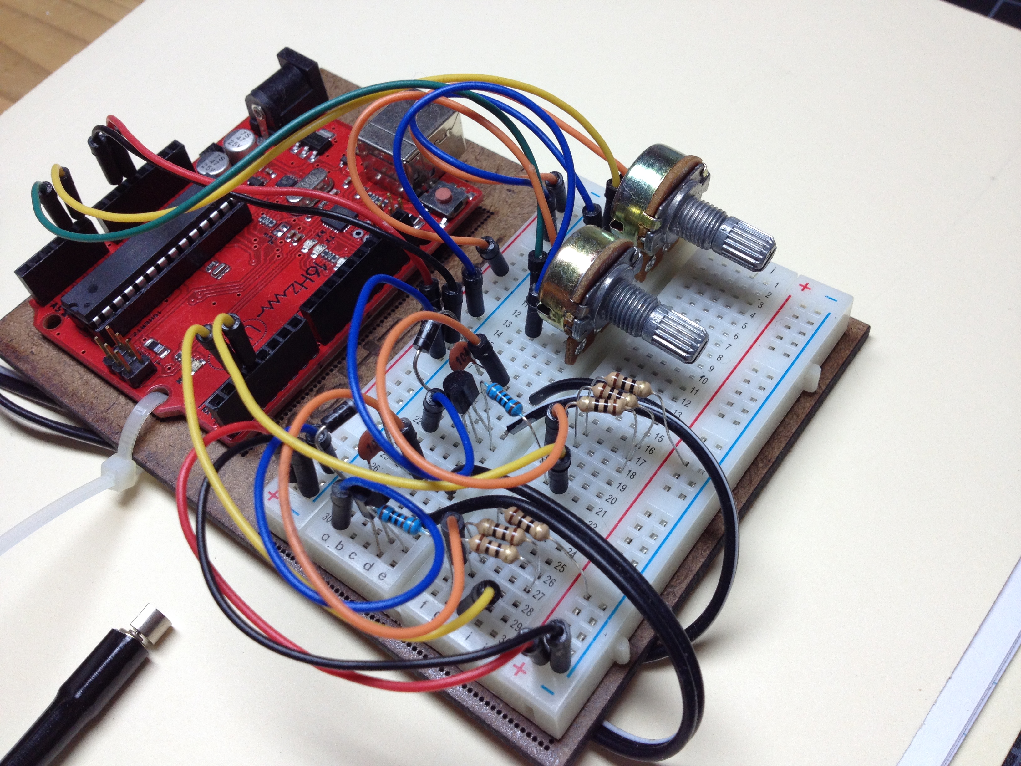
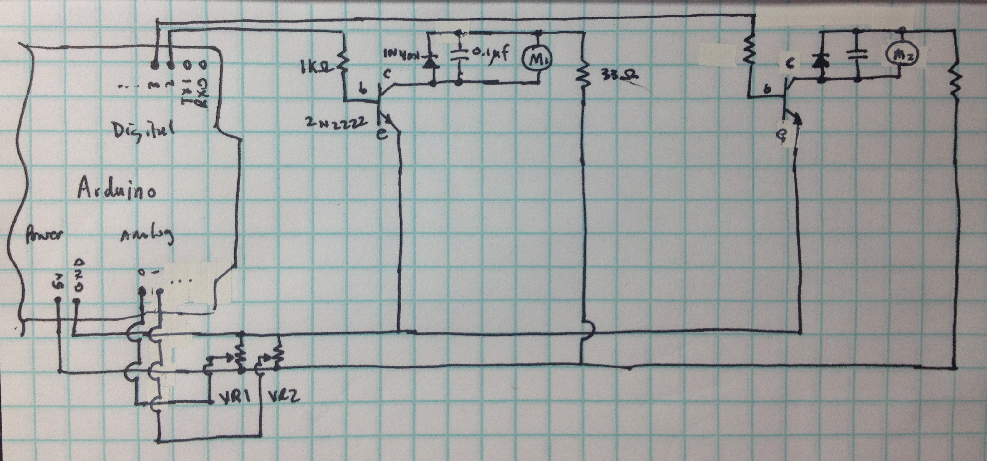
 This is basically a mashup of two standard Arduino projects - reading analog values from a pot, and controlling a piezo motor. The circuits are duplicated for left and right sides. The circuit diagram is here, and a picture of the assembled board is here.
Here is an example of the individual projects:
- Reading a pot: Reading a Potentiometer (analog input)
- Driving a piezo motor: Figure 8-8 of the Arduino Cookbook (Amazon link here).
Parts
- 2 x 1K Ohm resistors
- 2 x 2N2222 transistors
- 2 x 1N4001 diodes
- 2 x 0.1uF capacitors
- 2 x piezo motors, e.g., Micro Vibrating Motor Cell Phone Beam Bristlebot Robot 6x10mm
- 2 x 33 Ohm resistors
- 2 x 10K Ohm circuit board pots
Assembly
I used a basic Arduino breadboard - it was pretty straighforward. I didn't have any 33 Ohm resistors so I had to use 3 x 10 Ohm ones in series. For the motors I simply applied some heat shrink tubing for something to hold onto. I looked into more durable cases (I tried ping pong balls), but this worked OK for the prototype. See the pic here.
Code
The code manages four pins - two analog in ones for reading the pots, and two digital out ones for controlling the motors. The fifth pin is the built in LED digital out one that I pulse for effect. The pots are read by adjustPeriodAndDurationBasedOnPots() and saved into two variables: vibePeriod (how often the motor vibrates in ms: a range ~ [100 ms, 2000 ms]) and vibeDuration (how long the motor vibrates, in the same time range). The last variable is isCycleLedOn, which alternates between 0 and 1 with each cycle. After setup() initializes the pins, The standard Arduino loop() function just reads the pots (which sets the two control variables), cycles the first motor, and repeats for the second one. cycleMotor() turns on the motor, cycles the LED, waits the appropriate duration, then repeats to turn the motor off. Finally, adjustPeriodAndDurationBasedOnPots() reads the analog value from each pot (a value between 0 and 1023) and scales it to a range between ~100ms to 2000ms, which seemed to work pretty well. (Any faster was irritating, and any slower would have been boring :-)

Reader Comments